Introduction
The purpose of the insulator or insulation is to insulate the electrically charged part of any equipment or machine from another charged part or uncharged metal part. At lower utilization voltage the insulation also completely covers the live conductor and acts as a barrier and keeps the live conductors unreachable from human being or animals. In case of the high voltage overhead transmission and distribution the transmission towers or poles support the lines, and Insulators are used to insulate the live conductor from the transmission towers. The insulators used in transmission and distribution system are also required to carry large tensional or compressive load.
Here our brief discussion will be restricted to high voltage Insulators used in transmission lines and substations.
The HV/EHV insulators are broadly divided into two types based on the material used. One is ceramic and the other is polymer (composite) insulator. In Fig-A is shown the sketch of a porcelain disc insulator unit and in Fig-B is shown a glass disc insulator.
Traditionally ceramic insulators of porcelain are used in both transmission and distribution lines.
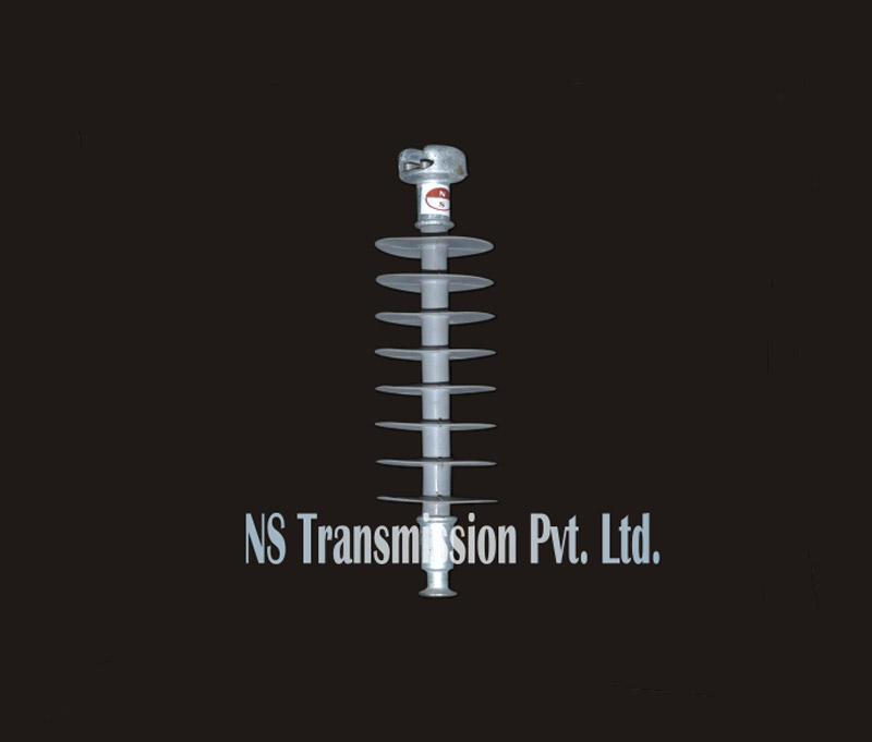
Now polymer or composite insulators are increasingly used in high voltage transmission systems. The polymer insulators have a fibre rod surrounded by outer sheath of some polymer. Due to the hydrophobic nature of the polymer insulator surface, dry areas are formed between wet areas resulting in discontinuities in wet creepage path. This phenomenon helps improve the performance of the polymer insulator in polluted and coastal areas. The polymer insulators has one great advantage that it is quite lighter in comparison to porcelain insulators. It is reported that the polymeric insulator surface degrade faster in comparison to porcelain insulator. One important disadvantage with porcelain insulator is that the porcelain insulators can bear large compressive force but less tensional force. The porcelain insulators surface is hydrophilic in nature, which means affinity for water. Polymer insulators age faster than ceramic insulators.

Below are few definitions in relation to insulator that one should know which are required here to understand some concepts.
Creepage Length -The creepage length is the shortest distance between two metallic end fittings of insulator along the surface of insulator . In the string of insulators for creepage length calculation the metallic portion between two consecutive insulator discs is not taken into account.
The corrugation below the insulator is for the purpose of obtaining longer creepage path between the pin and cap. The corrugation increases the creepage length so consequently increasing resistance to the insulator leakage current. The leakage current that flows through the surface of insulators should be as little as possible.
The creepage distance required in clean air may be 15 mm per kiloVolt (line voltage). In the polluted air depending on the level of pollution of air the required creepage distance increases.
Flashover distance – It is the shortest distance through air between the electrodes of the insulator. For a pin type insulator shown in Fig-C the double headed red arrow line is flashover distance.
Flashover voltage – The voltage at which the air around insulator breaks down and flashover takes place shorting the insulator.
Puncture voltage – The voltage at which the insulator breaks down and current flows through the inside of insulator.

An insulators may fail due to excessive electrical stress, excessive thermal and mechanical stress or degradation due to environmental chemical action of surface of the insulators. The electrical failure can happen between conductor and earth through air or through the volume of insulating material. In one case due to excessive electric stress the insulator may fail when a flashover takes place through the air between the conductor and tower. In other case the insulator may be punctured through the volume. The insulating materials say porcelain has high dielectric strength in comparison to air. The insulator are designed so that it will flashover before it gets punctured. Failure due to flashover is generally temporary and self restoring. But failure due to insulation puncture is permanent and the insulator is damaged and required to be replaced. An insulator which have internal defects like voids and impurities, reduces the electrical strength of the insulator.
The flashover may results in damage of insulator glaze which can be repaired. In polluted regions contaminants deposit on the surface of the insulator that results in reduction of the flashover voltage of the insulator in wet condition. For example if the power frequency flashover voltage of a 33 kV pin insulator is 95 kV in dry then in wet condition the flashover voltage may be reduced to below 80 kV. Insulators are designed to withstand flashover voltage. In this example you can observe that even in the wet condition the flashover voltage (80 kV) is more than twice the insulator working voltage (33 kV).
The other important electrical parameters of insulator are Electromechanical failing load, lightning withstand voltage and switching impulse withstand voltage etc.. HV Line insulator requirement is based upon the creepage length. The switching impulse withstand voltage is particularly more important in case of Extra High Voltage (more than 300 kV) and Ultra High Voltage lines.
Insulators of different design are available for different applications some cases are outlined below.
Suspension Insulator
The suspension insulators are used to support conductors in high voltage transmission lines. The suspension insulators string used in transmission lines are obtained by joining several disc insulator units. according to the type of hardware fittings, usually two varieties of disc insulators are used in HV transmission line. These are cap and pin type and ball and socket type. A porcelain cap and pin disc insulator is shown in Fig-A. Also in Fig-B is shown a glass disc insulator. In the porcelain insulator the somewhat umbrella like upper part called skirt is glazed and smoothened so that when it rains the dust and salt deposited on it are easily washed away. The contaminants cannot easily penetrate the glazed surface. When it rains the lower corrugated part does not wet and remains dry. This dry portion is the effective creepage length in wet condition.
In the transmission line a string of disc insulators are formed by fitting the pin of one disc to the cap of next disc. Simply by adding more numbers of discs in the string the insulator string is used for higher voltage. Moreover when one disc is damaged only that particular disc is replaced not the whole string.
Pin Type Insulator
The pin type insulators are suitable for use in low and high voltage distribution systems. Actually in distribution lines you will hardly find any other type of insulators. Pin type insulators are not usually used above 33 kV as the insulator size will become large and costly and unfeasible. See the figure-C for a pin type insulator.
Post Insulator
The post type insulators are mostly used in high and extra high voltage substations. In the substation Post type insulators are used for supporting equipments and Bus conductors. See Figure-D for a post type insulator.

The post insulator is manufactured as single unit from porcelain or composite material. The post insulators are also required to have sufficient bending strength and torsional strength. Both porcelain and polymeric post type insulators are used in practice.